In this post, We will configure Logical Routing and Switching in NSX-T including Static Routes to the outside network.
This is the lab network setup I’m referring to.
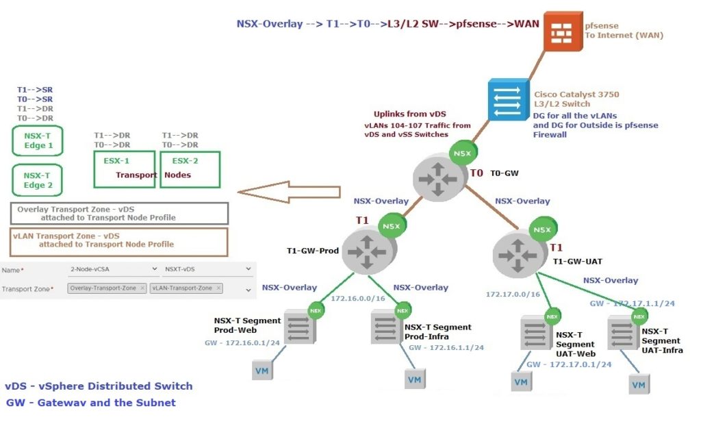
Before getting into the NSX-T configuration let’s review the physical/virtual network setup and configurations
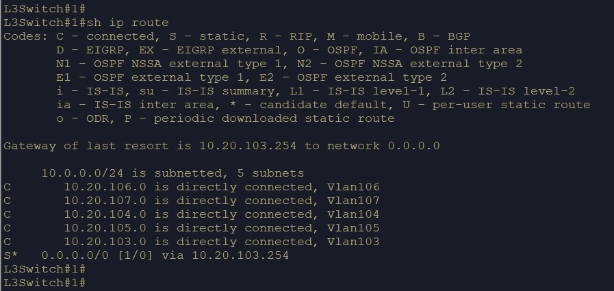
My ToR Switch (Cisco Catalyst 3750) configurations (L2 and L3 functionality)
- For vLANS 105-107, the default gateway is configured on my ToR Switch (vLAN Interface IP Addresses and IP Routing is enabled on the Switch)
- The default route is configured to forward traffic to pfsense Virtual Firewall’s LAN Interface IP Address (10.20.103.254) (pfsense connects to the Internet)
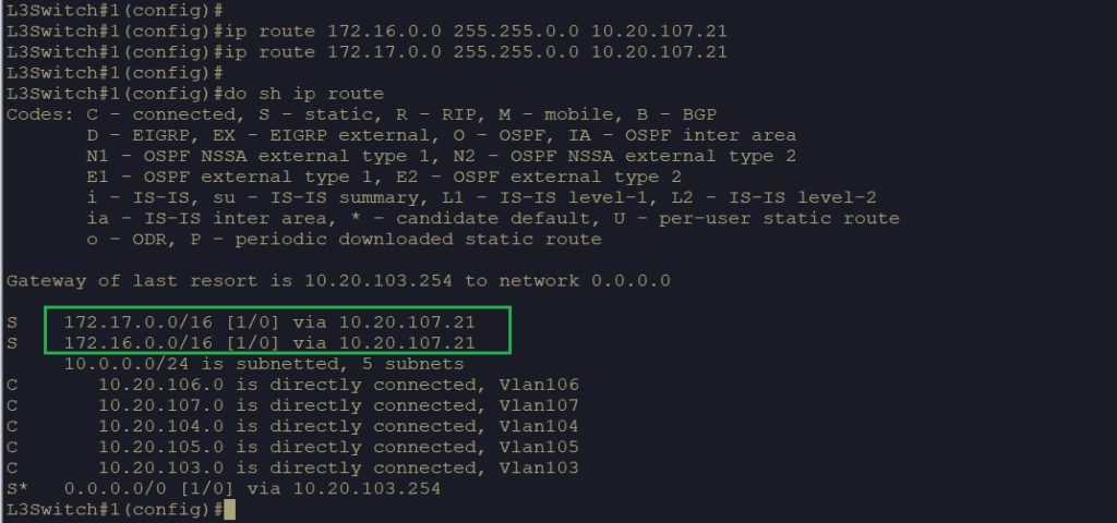
- Static Routes to NSX-T segments will be configured later for 172.16.0.0/16 and 172.17.0.0/16 networks
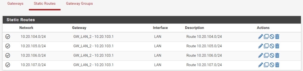
pfsense Configurations
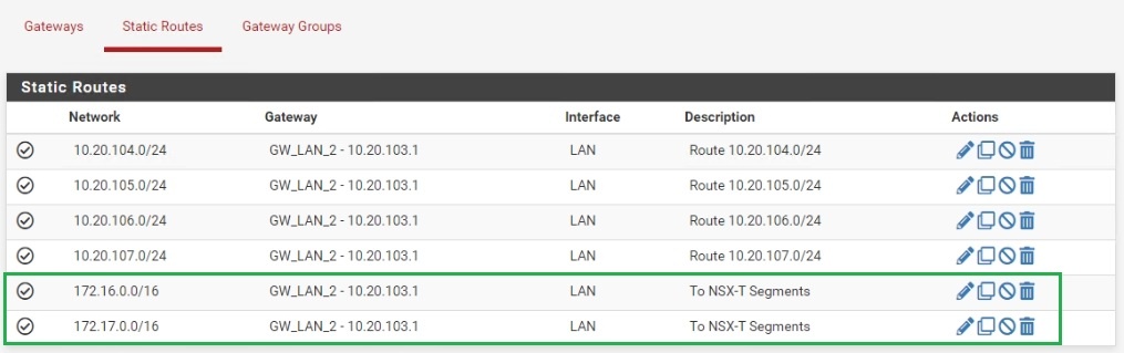
- The static route has been configured to reach the internet, Also to the vLANs that are configured on the switch to reach from outside
- Static Route to NSX-T segments will be configured later for 172.16.0.0/16 and 172.17.0.0/16 forward to vLAN 103’s default gateway (10.20.103.1)
Now is the time to configure our NSX-T. I have listed my naming convention here, which I will be using for the configuration,
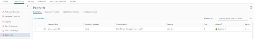
- Edge-VLAN-107 – VLAN-Backed Segment
- T0-GW – Tier-0 Gateway
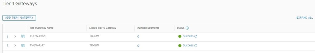
- T1-GW-Prod – Tier-1 Gateway for Production Network
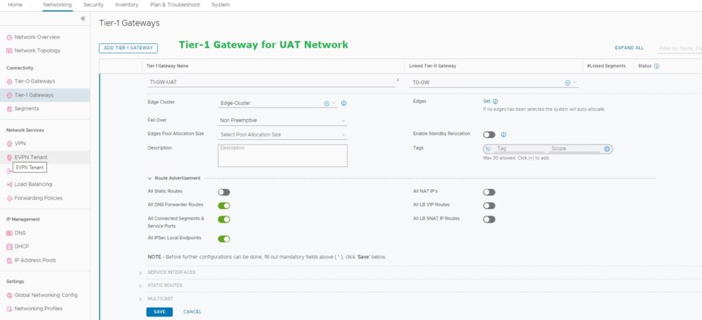
- T1-GW-UAT – Tier-1 Gateway for UAT Network
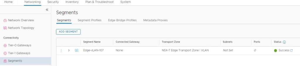
1. Create a vLAN-Backed segment for T0-Gateway External Interfaces to carry traffic to outside NSX-T and will name as “Edge-vLAN-107”
Networking – Connectivity – Segments
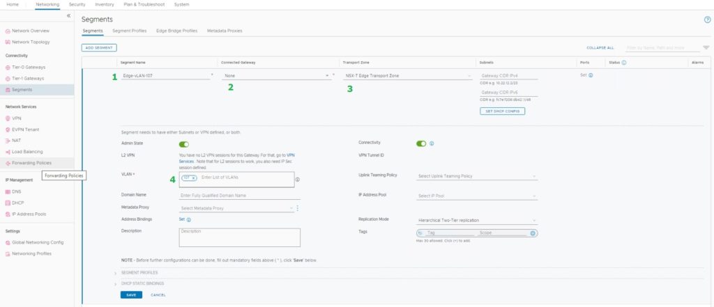
- Name of the vLAN-Backed segment
- We don’t connect to these vLAN-Backed segments to gateways since their default gateways reside outside of the NSX-T
- Select the Transport Zone (This vLAN Transport Zone configured in Edge Uplink Profile)
- Configure vLAN ID
Note: In this lab, I’m not using vLAN-Backed segments for VMs since I don’t have any use cases. But if you want to apply NSX-T Distributed Firewall Rules for your normal VM Port Groups (vDS Port Groups) you can create vLAN-Backed segments using vLAN Transport Zone we created. The only difference is we won’t configure GW on the NSX-T side.
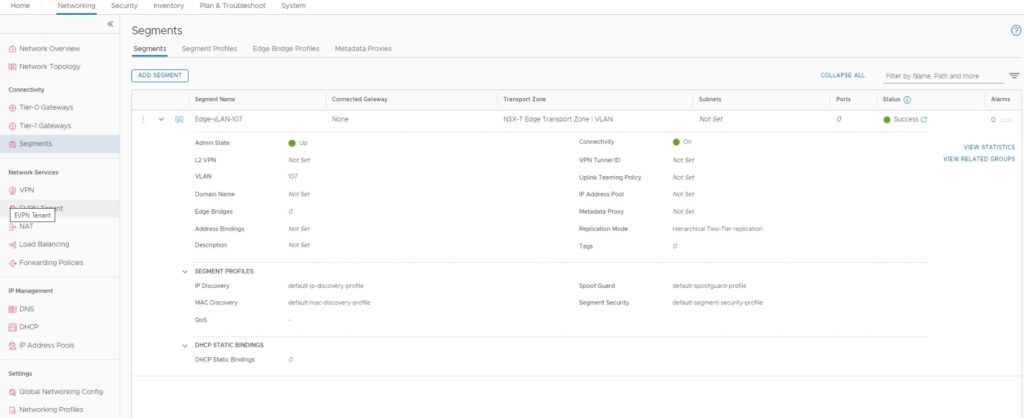
I have used all the default Segment Profiles as you can see in the above.
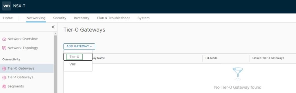
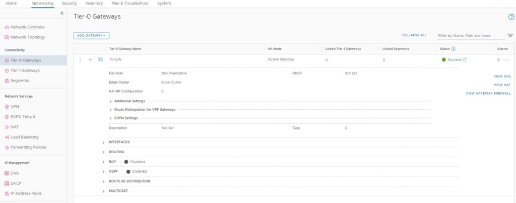
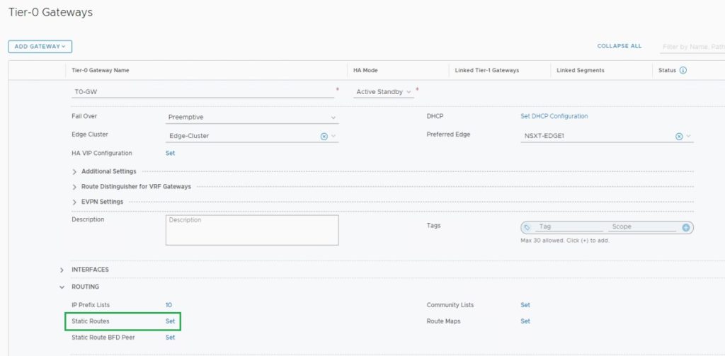
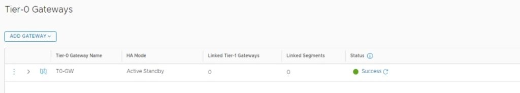
2. Configure T0 Gateway (T0 Router)
Networking – Connectivity – Tier-0 Gateways
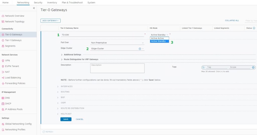
- T0-GW – Name of the T0-Gateway
- Edge-Cluster – Name of my Edge Cluster deployed earlier
- HA Mode for T0-Gateway (I’m using Standby Mode since it’s a Lab environment. according to your NSX-T Design you can choose the T0-Gateway HA Mode)
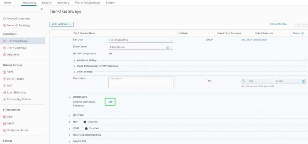
I disabled the BGP option since I’m using a static route in my lab. Now We need to configure External Service Interface (One or two per NSX-T Edge Node, Since We, choose to use T0-Gateway as Active-Standby Mode, I will only create one External Service Interface), I have discussed this in previous posts. Depending on your NSX-T, T0-Gateway design you can decide the configuration.
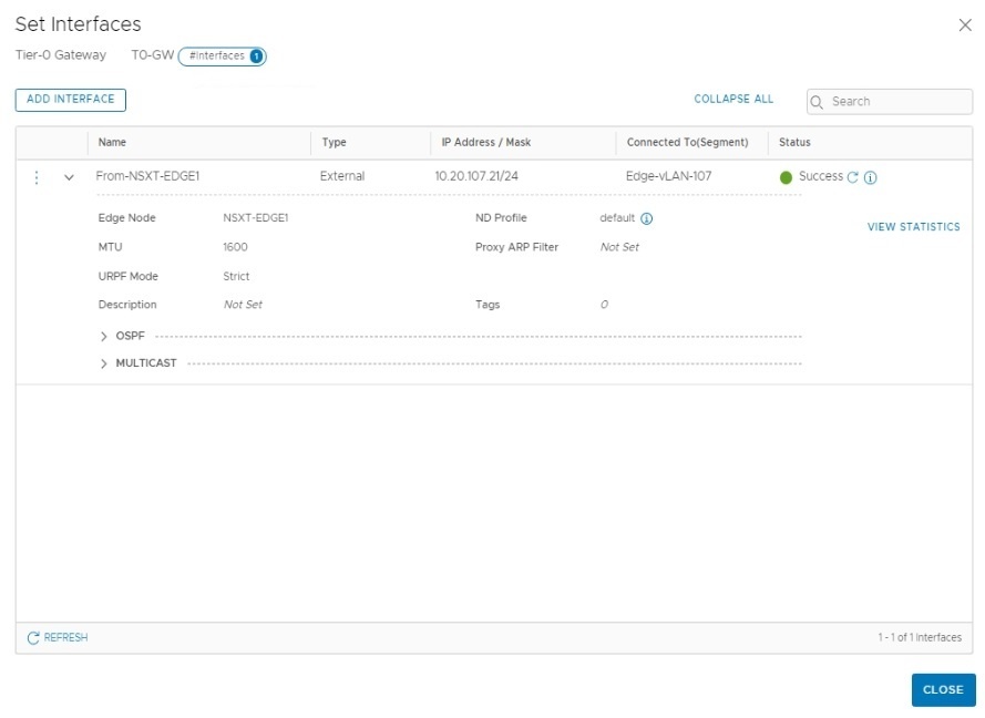
Edit your T0-Gateway and go to the Interfaces and click on “Set” External and Service Interfaces
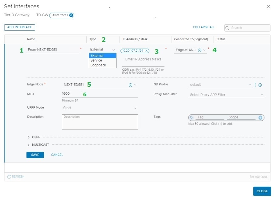
- Name of the Interface – “From-NSXT-EDGE1”
- Interface Type – “External”
- IP Address for the Interface has to be from the vLAN 107 Network – “10.20.107.21/24”
- Connected Segment – “Edge-vLAN-107”
- NSX-T Edge Node – “NSXT-EDGE1”
- MTU – “1600”
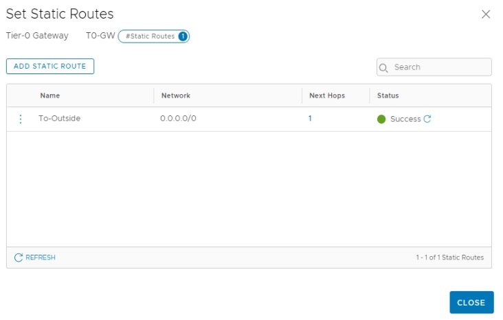
The final configuration on T0-Gateway is to set up a Static Route to reach outside
Edit your T0-Gateway and go to the Routing and click on “Set” Static Routes
Then click on “Add Static Route”
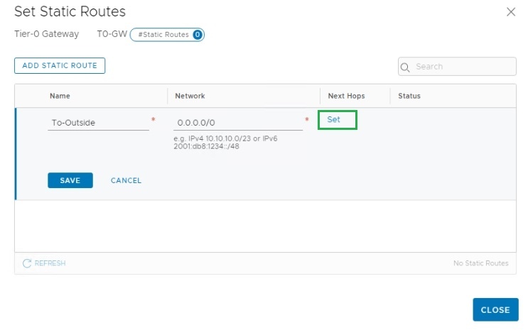
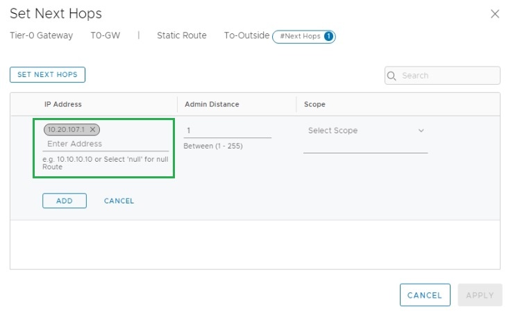
The next hop is the vLAN 107’s interface IP address configured on ToR Switch. This vLAN is part of the External Interface configuration.
3. Configure T1 Gateways (T1 Routers)
Networking – Connectivity – Tier-1 Gateways
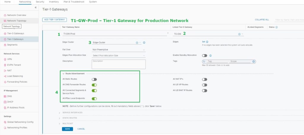
- Name of the Tier-1 Gateway
- Attached, T0-Gateway
- Attached, is Edge Cluster
- Route Advertisement (What are networks should advertise to T0-Gateway)
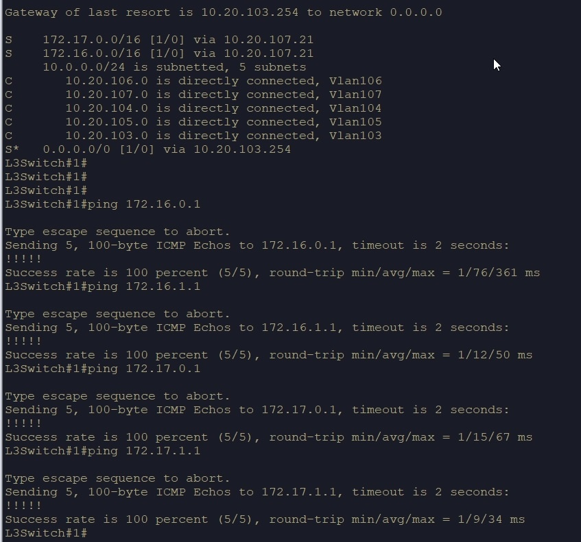
Now, need to configure static routes on the ToR switch and pfsense firewall to reach 172.16.0.0/16 and 172.17.0.0/16 NSX-T Overlay segments which will create next.
Note: Since I only have a single ToR switch I don’t configure two external interfaces for redundancy. Therefore It’s a single external interface attached to the “NSXT-EDGE1” edge node. But in real-life scenarios, It would be two or more external interfaces according to your high availability design.
4. NSX-T Overlay Segments
Networking – Connectivity – Segments
Following segments, we will be created in NSX-T,
- Production Network NSX-T Segments – CIDR – 172.16.0.0/16 , Prod-Web (172.16.0.0/24) / GW – 172.16.0.1, Prod-Infra (172.16.1.0/24) / GW – 172.16.1.1
- UAT Network NSX-T Segments – CIDR – 172.17.0.0/16 , UAT-Web (172.17.0.0/24) / GW – 172.17.0.1, Prod-Infra (172.17.1.0/24) / GW – 172.17.1.1
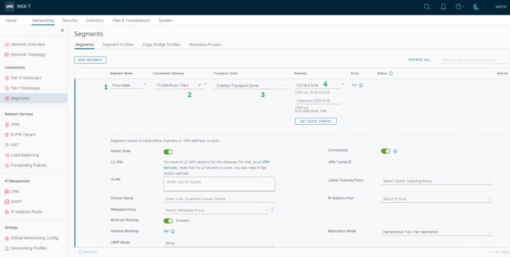
- Overlay segment name – “Prod-Web”
- Attached T1-Gateway – “T1-GW-Prod”
- Transport Zone – “Overlay-Transport-Zone”
- Subnet – “172.16.0.1/24” (Subnet with the default gateway as 172.16.0.1)
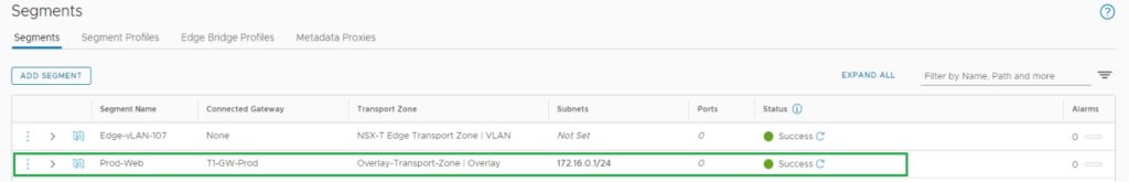
Rest of the settings I choose to use the default configurations. Also, I will finish the rest of the segments configurations since they will be the same as the first one. The only difference is for the UAT segments you need to select the T1-Gateway as T1-GW-UAT.
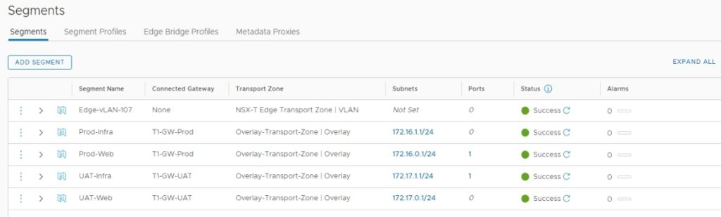
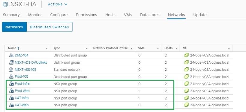
As you can see in the vCenter under Networks NSX-T segments have been created.
We have successfully configured the NSX-T configuration for us to test the East-West and North-South connectivity with a few VMs deployed. I have tested the connectivity from my ToR Switch to NSX-T segments and vice versa.
* Screenshots captured from VMware vCenter Console and NSX-T Manager Console on Jan 09, 2022.
