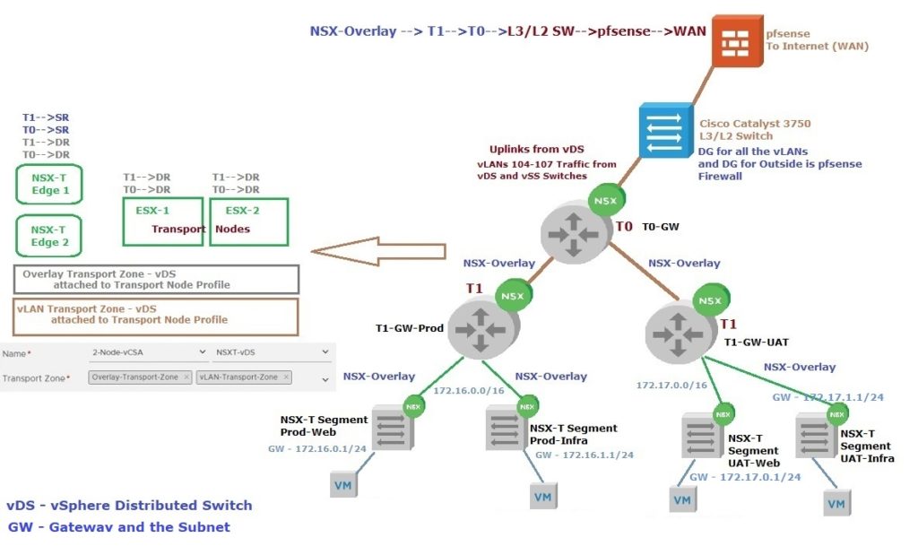
Logical Router, (T0/T1) Basics
The NSX-T Logical Router is the entity that allows traffic to flow East-West and Egress Out (North-South) to Public Networks. The Logical Router is a virtualized device that is distributed across the ESXi/KVM Hosts (Transport Nodes).
Within NSX-T, there is the concept of Tiering Routing Topologies so that Multiple Tenants can be given control of their own routing services and policies and NSX-T administrators can control services and policies above the tenant layer.
This structure is as follows;
Tier-0 Logical Router (Tier-0 Gateway) – Top-tier router that interfaces with the actual physical network in the north end of the Tier-0 interfaces. This is where dynamic routing protocols (BGP) can be configured to exchange routing information with physical routers. The south side of the Tier-0 routing topology connects to the Tier-1 routing layers of the tenant routing topologies and receives routing information from them. The Tier-0 routing layer pushes the default information to the Tier-1 routing layer
Tier-1 Logical Router (Tier-0 Gateway) – The northbound interfaces of the Tier-1 layer connect up with the Tier-0 layer for public networks access, while the southbound interfaces hook into the Logical Switches that are created by tenant administrators
- Logical Router (T0 or T1), Distributed Router aka DR and Service Router (Lives on NSX-T Edge Nodes) aka SR. Still technically Single Router
- East-West Routing occurs via DR Component, Located on each ESXi/KVM Hosts (Transport Nodes)
- Tier-0 Distributed Router (T0-DR), basically will handle the First Hop Routing and is used for North/South Routing occurs on SR Component (NSX-T Edges)
- Distributed Router consists of Distributed Routing Components and centralized components called Services Router (SR). DR Routing Components running as Kernel Modules in each Transport Nodes as well as in Edge Nodes
There are two primary options for Routing in NSX-T,
- Single Tier Routing
- Multi-Tier Routing
NSX-T, Single Tier Routing Architecture
- Tier-0 Distributed Router (T0-DR), basically will handle the First Hop Routing and is used for North-South Routing
- Distributed Router consists of distributed Routing components and centralized components called Services Router (SR). DR Routing components running as Kernel modules in each Transport Nodes as well as in NSX-T Edge Nodes
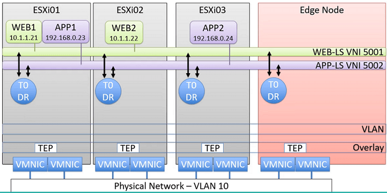
Services Router
If any of these below Services need to be configured in NSX-T, NSX-T Edge Node needs to be deployed, which is hosting the Service Router. SR will connect to External Networks (Out Side of the NSX-T). Can be configured with Dynamic Routing using BGP or Static Routing
- North-South Routing
- NAT
- DHCP
- Load Balancing
- VPN
- Gateway Firewall
- Bridging
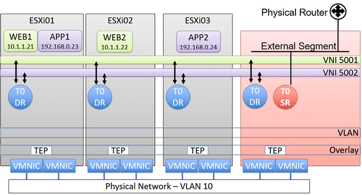
Inter Tier Transit Link (Transit Network), Basically connecting Distributed Router (DR) to Service Router (SR) for North-South Routing (North Bound Network), Also connects Tier-1 Gateway Router with Tier-0 Gateway
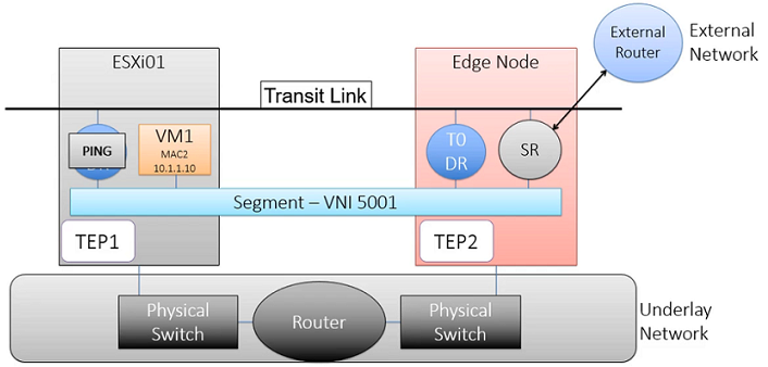
NSX-T, Multi-Tier Routing Architecture
- Multi-Tenant Support
- The logical separation between Provider Router and Tenant Router
- The top Tier is the Tier-0 Gateway and the bottom tier is the Tier-1 Gateway
- The Tenant has complete control of Tier-1 Gateway Routing
- It’s not mandatory but recommended
Tier-0 Gateway (Tier-0 Distributed Router / Provider Router)
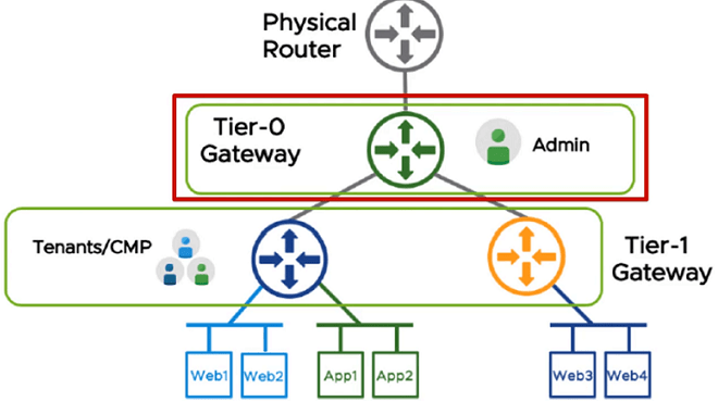
- Provide connectivity between different Tenants
- Firewall Rules, Controlled Route tables
- South Bound to Tier-1 Gateways (Tier-0 Gateway can connect one more Tier-1 Gateways) and North Bound to Physical Routers etc.
- Connect directly to Logical Segments (VNIs)
- Dynamic Routing using BGP or Static Routing
Tier-1 Gateway (Tier-1 Distributed Router / Tenant Routers)

- These are not Distributed Routers run on each Transport Nodes, But in Multi-Tenant these Tier-1 Gateways are used to do the East/West Routing between the tenants
- Don’t support Static or BGP Routing can only connect to Tier-0 North Bound
- Tier-1 Services Routers (Within Tier-1 Gateway) can be implemented to use NAT, DHCP, Load Balancing, etc. Services inside the tenant
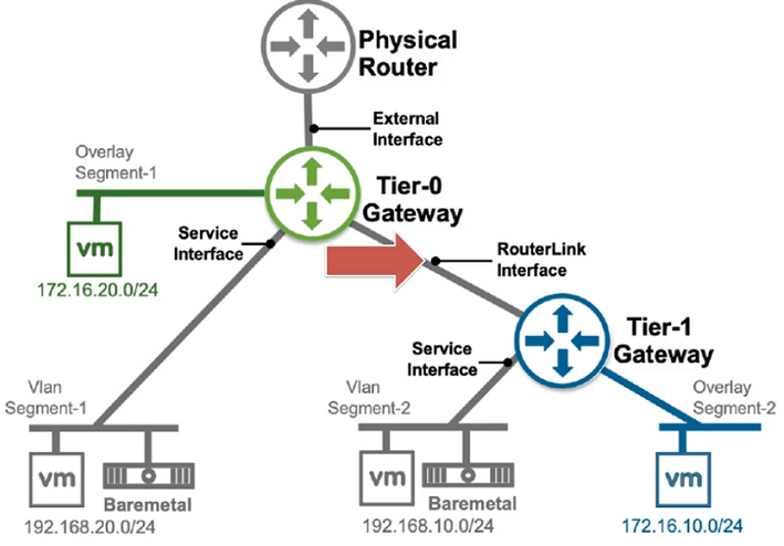
- Router Link Interface (Inter Tier Transit Link Network) will create automatically to connect Tier-0 Gateway and Tier-1 Gateway, Subnet for the Interfaces creates automatically. A subnet is starting 10.64.x.x.
Router Link Interface (Inter Tier Transit Link Network)
Service Interfaces
- These are Interfaces to connect to vLAN Segments, these are used to connect vLANs Physical and Virtual Workloads, also can be connected to Load Balancers. Supported on both Tier-0 and Tier-1 Gateways
- To connect Service Interfaces, you must have deployed Tier-0/1 Gateway Router (Service Interface is a centralized interface that resides on Service Router)
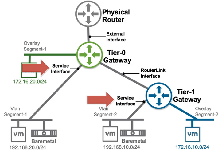
Tier-0 and Tier-1 Gateways can both be connected to Overlay Networks
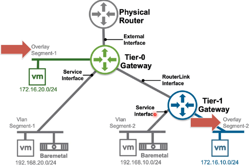
Routing Advertisement
Tier-0 Gateway Router learns Routes from Tier-1 Gateway Routers as well as its directly connected Interfaces and Redistribute to BGP (Basically advertise to directly connected Physical Routers)
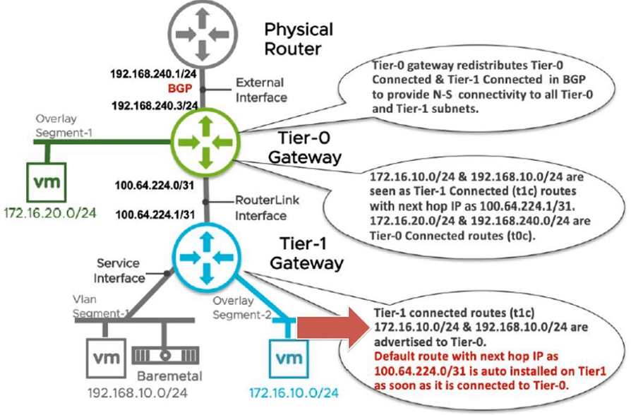
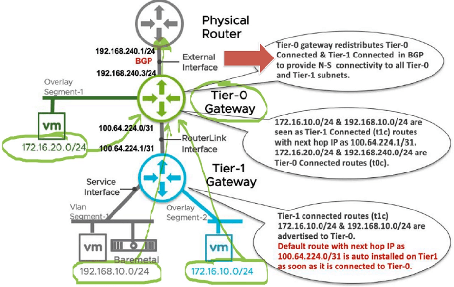
Note: These images have been taken from VMware’s NSX-T Reference Design Guide 3.0
I have included the diagram shown below to understand the T0 and T1 Logical Routers (Gateways) and My Lab’s Network Setup. In that diagram, the Left Side represents where these DR/SR Routers placement on NSX-T Edges and Transport Nodes. On the Right Side is My Lab Setup’s Network setup.
